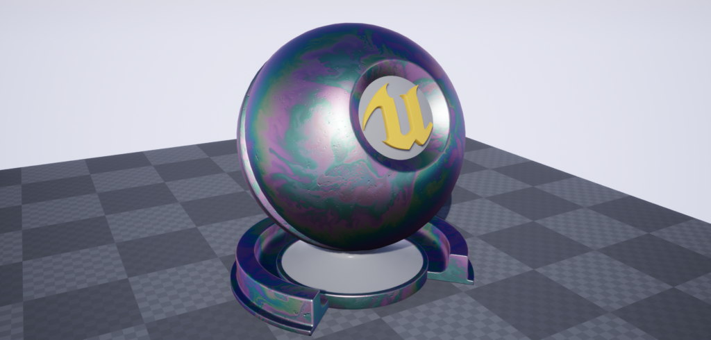
Thin Film Interference is an optical effect caused by the constructive & destructive interference of light waves as they pass through a thing medium. This only occurs when the thickness of the film is in the range of visible light (so 380nm-780nm, approximately).
This video is marginally tangential, but explains the basics well:
The paper is fantastic, and the results have since been implemented in Unity & UE4.
However, the shader is expensive. Whilst it is a practical and wonderfully accurate shader, it would not be something I would suggest for lower-end platforms.
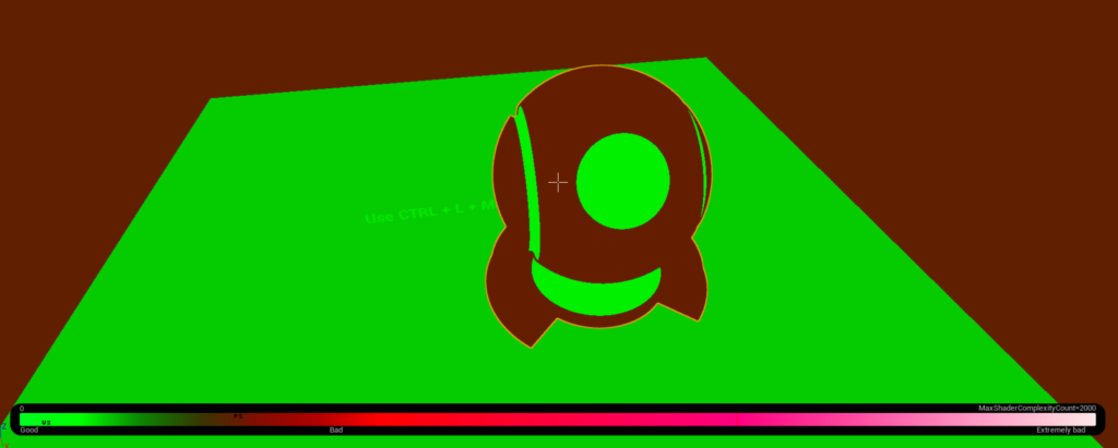 Realtime thin film interference is heading towards bad.
Data Extraction
What I wanted to do was to find a reasonable way of approximating the colous and results from the shader, but at less expense.
The first step is to extract the effect to individual planar tiles, so that we can break down what the physical values in the shader produce in isolation.
The next step was to make the inputs for Dinc (thickness), n2, n3 and k3 based off UV coordinated and world space coordinates – that way, I can arrange planes in a grid to use as a look-up texture. For this example, I fixed the normal to be (0,0,1) and the light direction to be (0,0,1).
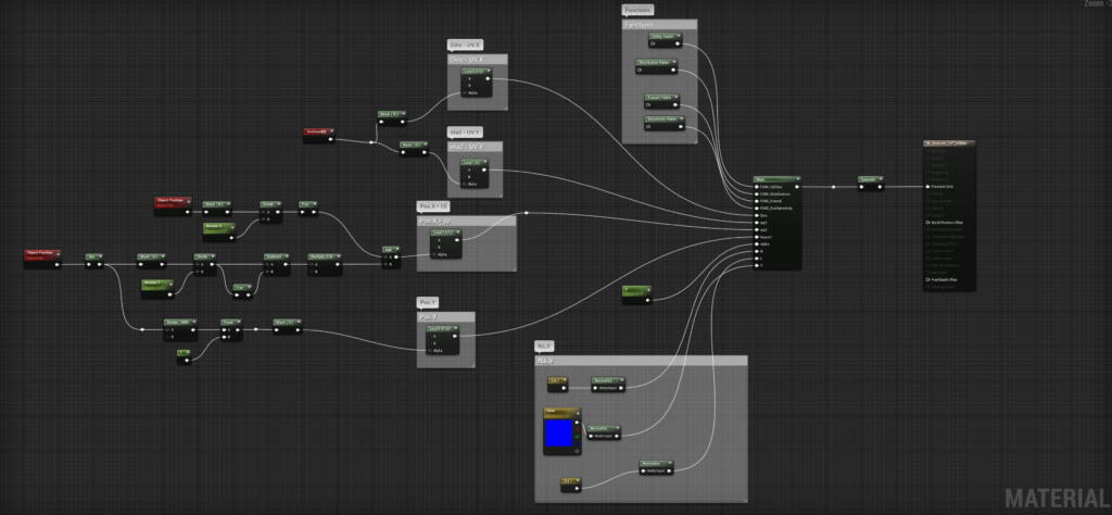
And this is the scene setup – each one of these is a plane, set to 16.0 scale in the X-axis. They tile across the +X and -Y axis.
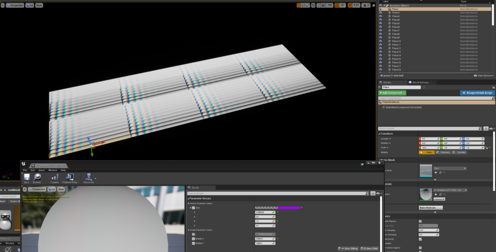
I then took a High Resolution Screenshot of this to create a look-up texture, like so:
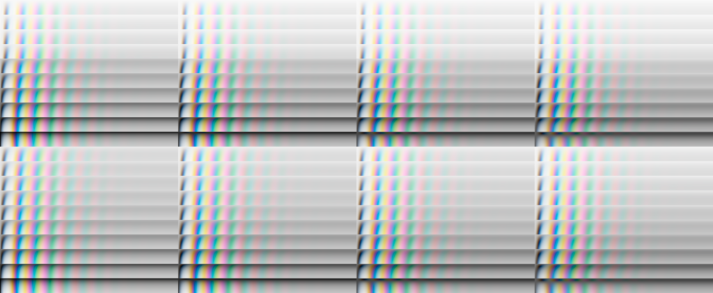
As you can see, the changes in brightness and saturation all vary based on the input properties – it appears subtle, but it adds up across the range of possible values.
There is, however, one more value we can’t fit into a LUT – the viewing angle. This also has an impact on the final colors – I’ve exposed the light direction here to hopefully show the impact it has:
Changing the Light Direction
We can simulate this effect by offsetting our UVs later.
I imported the LUT setting ‘No Mipmaps’ and ‘Nearest’ filter, as we want no blurring between the grid cells.
Approximating
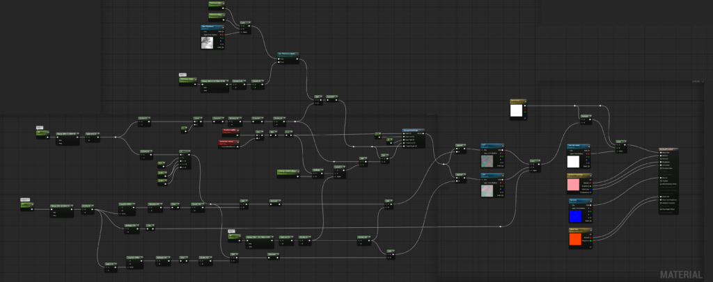
I then set it a new Material in such a way that the input values for Dinc, n2, n3 and k3 all correspond to UV coordinates in the LUT – I use a Fresnel function (dot(N,L)) to sample the LUT. Where you see the inputs in the Material Graph, the next few nodes for each are simply remapping the value ranges into UV space.
I sample the texture twice for k3 and blend between the two samples, as one sample didn’t give me enough precision.
Next, I added in option use a thickness mask, or a thickness value.
Finally, to mask the effect, we need to multiply our underlying base color by the thin film color, as the light waves bouncing off the underlying surface will only reflect back with that surface color. We then blend this using a mask, so we can mask out areas we don’t wish to apply the film effect.
The full Material
Results
We can now achieve some mightily convincing results:
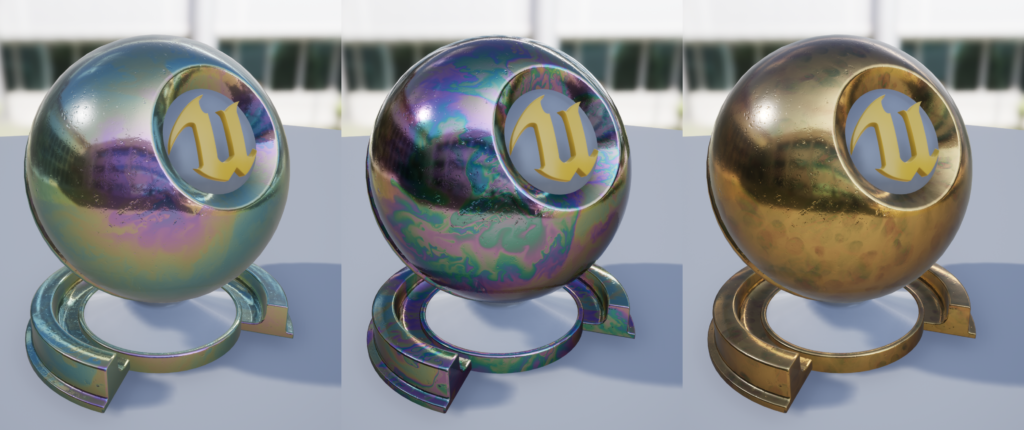
And if you want to really go-to-town, this sort of thing is completely possible:
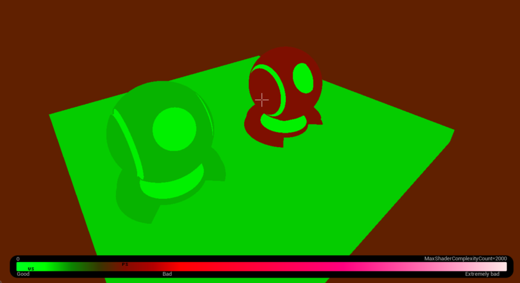
And there is also a difference in instructions: from 440, down to 198, and this difference doesn’t even account for the fact that the more expensive shader hasn’t had support for film thickness mask etc. added yet…

Shader complexity view:
Concluding Notes
My implementation isn’t full simulation – its not designed for physically-accurate work. It is, however, close, and more importantly, cheap – enough for mobile/low-end applications if you can handle the additional memory requirements for the LUT.


