There is no excerpt because this is a protected post.
YCoCg Compression
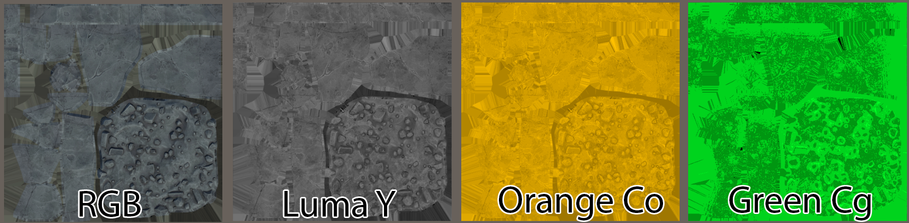
Introduction When seeking to save on memory, one approach is to reduce texture file sizes. This is because textures are typically the largest user of memory. Usually, texture size can be reduced through: Textures are typically stored in the format of RGB (red, green & blue) intensities, as this replicates the three color primaries of light that our eyes are sensitive to (and the typical primary colors on displays). However, our eyes are more sensitive to luminance (or “brightness”) than they are of raw color. Take the following image as an example, here you can see a source image broken up into its luminance and color components: As you can see, your eyes are much more sensitive to the center image than the right. In fact, you can shrink the resolution of the color map down by an order of magnitude and you will struggle to see any difference. See the following: As you can see, even with 10x less color resolution, you will be hard-pressed to see any difference. This presents us an opportunity to save on texture memory if we extract the color information and reduce its resolution – we can reduce memory usage without affecting visuals. There are several color spaces that use luminance, which include CIE color spaces (such as Lab and Lch) and Y-spaces (such as YCbCr, YCoCg, YDbDr, etc). In theory, we can use any of these, but we should seek to use one that has a fast conversion back to RGB. This is because our shaders output to RGB and the color conversion has to be done in the shader stage. We therefore need a color space that has fast conversions. CIE color spaces use exponents and branching logic, making it expensive. YCoCg is the most ideal for us to consider, as it is lossless, uses fewer bits than others and is simple to code. YDbDr could also work, but its matrices are simply less human-readable. Terminology: Just to make things clearer, I’ll take a moment to explain the terminology: Y → This is the “luma” component. This is slightly different from “L”, which is the “luminance” component. Luminance is the brightness of a color, whereas luma is the perceived brightness. Luma is a gamma-corrected luminance value. See more here. CoCg → This refers to the two color primaries. Much like RGB is a record of the red, green and blue values of a pixel, Co and Cg refer to the distance a pixel color is from orange and from green. Consider Co and Cg as meaning how much a pixel color is the “color orange” and the “color green”. Process: What we then will look to do is: Converting RGB to YCoCg Converting an RGB pixel to YCoCg is fairly straightforward with a matrix: I shall put this in code-terms, which should hopefully make the above clearer if you don’t understand matrix multiplication: However, it is worth noting that as we are dealing with “luma”, and in Unity we will be importing these as linear textures, you must run your RGB values through gamma correction first: And that’s all we need to do to convert our textures… Well, sort of. The CoCg channels are -1 to +1 values, and we would lose a lot of precision if we remapped this to 0-1 (half our color information would be destroyed when we saved the image). So our final step is to create 4 values that correlate to:Co -1 to 0 Co 0 to +1 Cg -1 to 0 Cg 0 to +1 We can easily fit these into a 4-channel image file. Our final pseudocode looks like this: What is important to note is that our Y value and CoCg values should be separate files. This is so we can maintain the Y-value’s resolution, and reduce the CoCg resolution to as low as we can get-away-with in Unity. This is straightforward enough, but we’re not going to save much if we simply swap the Albedo RGB for Y + CoCg textures. This is because on Quest we are using ASTC compression, which means that the Y image and Albedo RGB will compress to a similar file size. We will only get the savings if we can put the Y image inside another texture. Handily, Unity’s default URP texture setup puts Metallic and Smoothness textures into the R and A channel of an RGBA mask image, and leaves the G and B channels free. This is done because older compression modes, such as DXT, decrease green and blue bit depths as your eyes are less sensitive to those colors, and so you lose precision if you these channels as masks. However, as we are using ASTC and linear textures, this isn’t a concern as they compress equally, and we can populate the G or B channel with our luma/Y image. Whilst we’re at it, Unity keeps a separate AO texture, rather than packing it. The reasons for this are rather esoteric, and are valid, but in the pursuit of texture compression, we can put this into our new mask setup. I am currently working on a development tool to test this more easily: YCoCg Shader Throwing together a shader in Unity in Shader Graph to test this is simple enough.We just need to make sure that we import the textures as linear (not sRGB); Step 1 is to unpack the texture, and set the CoCg components back to the -1 to +1 range: Step 2, we run the numbers through this even simpler matrix: Our final pseudocode looks like so: Here it is in action: Compression Results These results are based on the following original texture map settings: Albedo – 4096*4096, ASTC 6×6 sRGB compression, 9.5 MB Metallic/Smoothness – 4096*4096, ASTC 6×6 compression, 9.5 MB AO – 4096*4096, ASTC 6×6 Compression, 9.5 MB Total texture usage: 28.5 MB Mask Compression CoCg Compression CoCg Resolution Memory saving Result ASTC 6×6 ASTC 6×6 4096*4096 9.5 MB ASTC 6×6 ASTC 6×6 512*512 18.8 MB ASTC 6×6
Getting Started with Developing for Mobile VR
This post hopes to explain some key aspects of developing on the Meta Quest 1, 2 &3 (and similar devices such as the Pico 4) from a technical artistic standpoint. It will contain a series of best practices, common pitfalls and useful context. Unless otherwise stated, the term “Quest” will be used interchangeably for Meta Quest 1, 2 & 3 and any other mobile VR headset. The features from headset-to-headset may vary, but the fundamental architecture and platform is the same. These guidelines apply broadly too all mobile VR headsets, such as Pico 4. We’ll start pretty technical to give a solid understanding of context, then we’ll move into practical advice further on. Technical Performance Overview You cannot ship on the Quest store unless you are hitting 72fps* consistently (equivalent to 13.8ms per frame). Therefore, the framerate should always be prioritised over artistic fidelity, if you are outside the frametime budgets. You should encourage individual responsibility for the performance impacts of changes made to your project. The Meta Quest uses a mobile chipset. This has critical and important changes in comparison to more traditional desktop-class chipsets, in terms of the art pipeline and features. A mobile chipset is designed around power efficiency. As part of this, the architecture prioritises using smaller bandwidths when sending data to and from the CPU/GPU. * Media apps can target 60fps How the Quest Renders Mobile VR has some important difference to traditional desktop rendering. Here is a quick breakdown: It is important to note that the GPU runs in a parallel way. This means that one tile may be running a vertex shader, another may be running a pixel shader at the same moment in time. There are shaders that can “break” tiling, causing the GPU to render the entire image (“immediate mode rendering”), and not run in a tiled mode. We don’t usually encounter these, but custom geometry shaders can do this (so dynamic wrinkle maps are a non-starter). Another consideration is that vertex-dense meshes can cause slowdowns, as it has to evaluate all of the vertices against all the tiles. If you have dense meshes, it may be better to break these down into smaller submeshes – as long as you don’t increase draw calls too much – it is a fine balancing act, but one that pays if you put in the effort. Why is this important? Mobile VR chipsets are designed to optimize power usage, so you don’t run out of battery after 20 minutes. To do this, they have very small amounts of memory bandwidth, as this is power efficient. The knock-on effect of this, is that when the GPU and CPU are sending data, they can only do so in small packets of data (hence, the use of tiles). When we “resolve”, the headset is transferring a very large image from GPU to CPU and exceeds the available memory bandwidth. This causes a stall on the device (from 1-2ms for a full screen image), where you are doing no processing. Let’s go a bit deeper into that Resolve, its important we have a really clear understanding: Resolve Cost We have established that the smaller bandwidth available can cause a stall with large images. A resolve cost is roughly 1-2ms, which is 1/7th of your entire frame budget, and so reducing the total resolve cost is critical to your performance, and therefore, your ability to ship your VR project. As the device has to render to the screen at least once, you are already paying a single resolve cost before anything else has happened. A resolve cost is always an “additional” cost, for example, if you use it as a post processing pass, and your pass costs 3ms on its own, your total cost is 3ms pass + 2ms resolve, so 5ms total. This resolve cost also makes using traditional Deferred Rendering impossible. For deferred rendering to happen, the GPU has to render out several GBuffers – in a minimal PBR workflow, these would be: Deferred on a mobile VR headset is no – too many resolves! (As an aside, we also don’t use deferred because we can’t get smooth anti-aliasing from MSAA. With deferred we have to use approximate techniques like TXAA and FXAA, which are nauseating and/or need extra buffers to work.) This alone is 6 resolves, which is 12ms of your 13.8ms (87%) frame time budget before you have calculated anything (not even your gameplay or physics updates, or even run your actual GPU processing)! For this reason, Mobile Chipsets almost exclusively use Forward Rendering. Deferred Rendering can also create other issues in VR (that are outside the scope of this document). All of the above is true for most mobile chipsets – though mobile phones can typically render at lower resolutions and framerates, and don’t have some nuances of VR that I will discuss next, so the cost to resolve is typically not a huge issue. Subpasses Up until fairly recently, Unity and Unreal Engine didn’t make use of Vulkan Subpasses when rendering – these features are now available in Unity 6+ with the URP and from the Oculus fork of UE 4.26. Subpasses allows to get around quite a lot of the resolve issues mentioned above. In a nutshell, they allow multiple passes to be run across the tiles before we resolve them and store the final buffer. In more concrete terms, you can render your tile as you normally would, then pass it through a color-correction post effect before you store it – thereby avoiding the resolve cost. The Oculus UE 4.26 Fork blog post on this is worth a read: https://developer.oculus.com/blog/graphics-showcase-using-vulkan-subpasses-in-ue4-for-performant-tone-mapping-on-quest/?locale=en_GB As of writing, none of my projects have been using these versions (because I’m using Unity LTS, and subpasses aren’t in an LTS release yet), but you should look to make use of them if you can, as they can give you a bunch of effects without the resolve overhead. Its worth noting that subpasses like this will not work
Custom MIP Levels
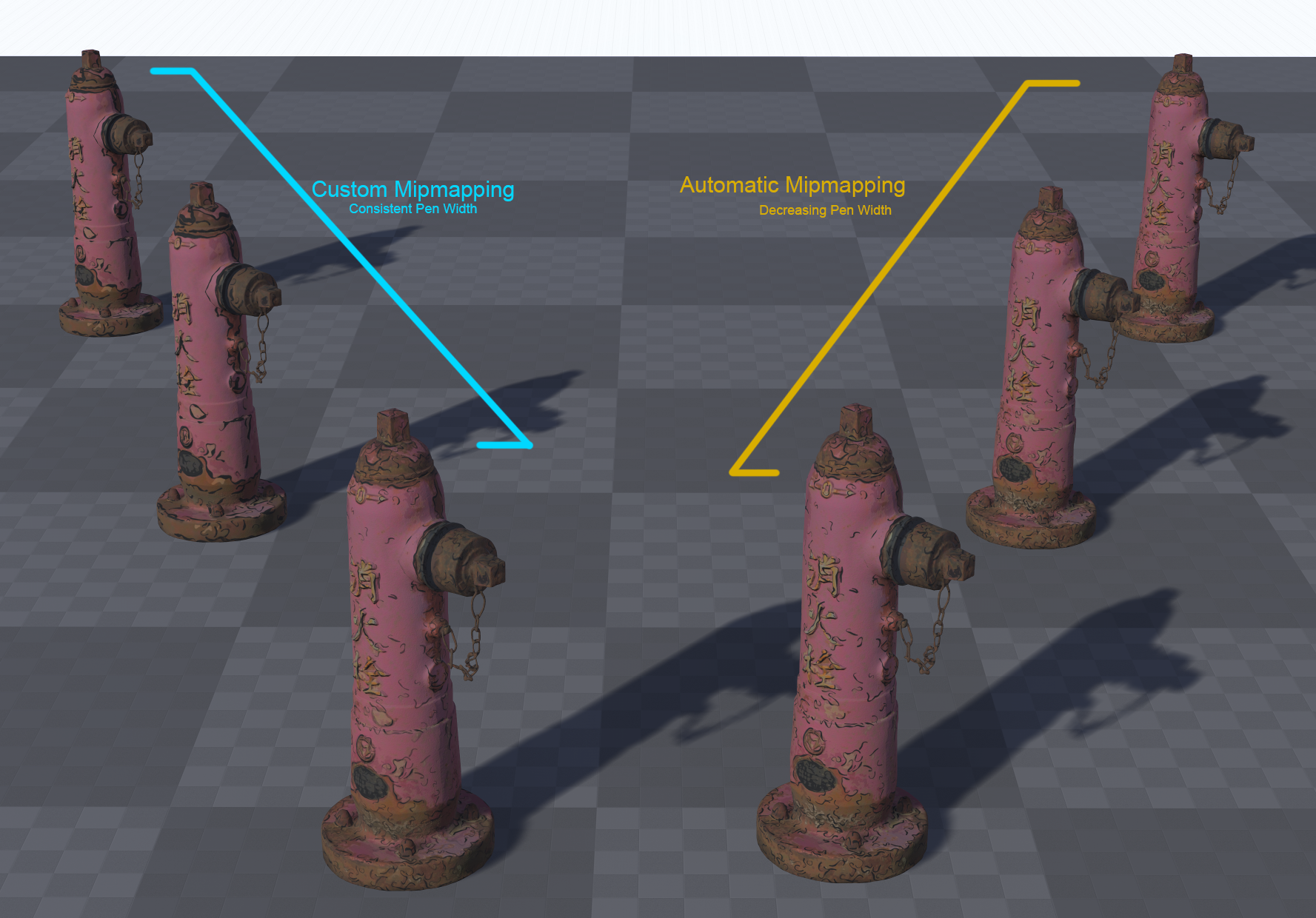
I wanted to research an easy way of creating every MIP level of a texture in Unreal (and any other engine), in such a way that I could create a unique image, or use custom filters or effects at every MIP level. This would let me create several effects, such as: Use custom filters where alpha is involved, such as chain-link fence or chicken wire, so that the wires look realistic as distance scales. Apply custom effects as things scale at distance, cheaply. For example, we could have a hand-draw sketch effect where pen width is more consistent at distance. Use custom filters where alpha is involved, such as chain-link fence or chicken wire, so that the wires look realistic as distance scales. Apply custom effects as things scale at distance, cheaply. For example, we could have a hand-draw sketch effect where pen width is more consistent at distance. In Action Left: Custom, Right: Default The advantage at doing this at a MIP level is that we can use a single texture sample, and the effect with automatically blend seamlessly without having to linearly interpolate between a whole bunch of texture. I tried a whole swathe of tools and techniques, most of which have problems. I’ll cover these quickly, just so you don’t have to go down the same rabbit holes that I had to: Intel Texture Works plugin for Photoshop. This supports MIPs as layers, which is useful in some ways. However, it does not export to an uncompressed DDS (8bpc, R8G8B8A8), which means we cannot import it into UE4, which accepts DDS, but only uncompressed, as it applies compression itself. NVidia Photoshop Plugins. This supports uncompressed DDS export, but it supports MIPs as an extension to the image’s X dimension, in one image. This makes modifying individual MIPs very tricky if you want to automate the process using Photoshop’s Batch feature. NVidia Texture Tools. This doesn’t support MIP editing at all. This leaves NVidia’s DDS Utilities, a legacy set of command-line tools. Turns out, these do exactly what we need, if we combine them with a bit of sneaky Python and DOS commands. NVidia’s DDS Utilities These utilities are just a bunch of executable files (.exe) that take some arguments and can combine images into MIPs for a single DDS. With that all out the way, let’s get started setting it up. Step 1: Prerequisites Getting Python Packages Step 2: Folder Setup Next we’re going to setup our folder structure – we’ll use these as a cheap way of managing the pipeline. One day, I’ll manage it behind a UI, but that’s a lot of work for a niche use-case. We’ll use four folders. “source” for source textures to generate MIP images from. “mips”, a directory to keep these new MIP images in. “dds”, where we’ll keep our files to let us convert our MIPs to DDS “OUTPUT”, for our DDS textures ready for our projects Make this structure anywhere on your PC. From your NVidia DDS Utilities installation path, copy these files into your /dds folder: Step 3: Creating MIP Images Now we can start. The first step is to create a set of images for each MIP level, so we can manually edit each MIP image later. To do this, we’ll use Python and the Python Imaging Library, and a batch file. Head into the /source/ directory and create a new Python file, generateMips.py, and a batch file, genMips.bat. First, let’s do the Python. Open the file in your favourite text editor, or IDE, and type the following: import sys from PIL import Image droppedFile = sys.argv[1] img = Image.open(droppedFile) srcSize = img.size path = “../mips/” name = droppedFile.split(“.”)[0] img.save(path+name+”_00.tif”,format=”TIFF”) mipNum = 1 print(“Loaded “+droppedFile+”, mipping…”) while srcSize[0] > 1 and srcSize[1] > 1: newSize=(int(srcSize[0]/2),int(srcSize[1]/2)) resized = img.resize(newSize,resample=Image.BILINEAR) newName=”” if mipNum < 10: newName=path+name+”_0″+str(mipNum) else: newName=path+name+”_”+str(mipNum) resized.save(newName+”.tif”,format=”TIFF”) srcSize = newSize mipNum=mipNum+1 As you can see, nothing too scary. I simply create a new image file at half the resolution of the previous file saved, until we hit 1×1 pixel. You can choose a different a different resample if you want, but we’ll be manually changing the files, so for now, it doesn’t matter. We take the image as an argument, this is so we can automate it externally if we want to – in our case, I want to make a batch file that I can drop a file on to and it will parse it with the Python script. In the batch file add this: generateMips.py %~nx1 pause This will take whatever we drop on top of the batch file and make new images for each MIP level in the /mips/ directory. Give it a go. Drag and drop Wait a short second… Boom! Images as MIPs! Step 4: Edit MIPs This part is on you. You can edit your MIPs as you like. One suggestion, if you want to use a filter is to create an Action in Photoshop, and use File->Automate->Batch to apply that action and save out. The important thing here is that your file had just one underscore, before the MIP index, for example In this case, I’ve called it normal, but it doesn’t matter. My output goes into the /dds/ folder, this is where you want your modified MIPs. Step 5: Generate DDS In that output, create two batch files – we need two as one is for Linear textures (for masks, etc.) and one for sRGB/gamma corrected for albedo and colour textures. Create two batch files from your text editor/IDE called: Here is the content for GenerateDDSColour.bat: nvdxt -quality_normal -nomipmap -pause -all -u8888 -gamma .\dds_dir set str=%~n1 for /f “tokens=1,2 delims=_” %%a in (“%str%”) do set stitchName=%%a&set sfx=%%b echo.stitchName: %stitchName% stitch %stitchName% md “..\OUTPUT” >nul 2>&1 copy %stitchName%”.dds” “..\OUTPUT” del %stitchName%* pause and this into GenerateDDSLinear.bat: nvdxt -quality_normal -nomipmap -pause -all -u8888 set str=%~n1 for /f “tokens=1,2 delims=_” %%a in (“%str%”) do set stitchName=%%a&set sfx=%%b echo.stitchName: %stitchName% stitch %stitchName% md “..\OUTPUT” >nul 2>&1 copy
Character Clothing – Part 4: UE4 Logic
Table of Contents Character Clothing Zone Culling Character Clothing – Part 2: Maya Character Clothing – Part 3: UE4 Shaders Character Clothing – Part 4: UE4 Logic Blueprints First, create a new Actor Component Blueprint Call it “BP_MeshZoneCulling” and open it up… Next to it, create a Enumeration, call that “ENUM_Cullzones” Open up the Enumerator and add in 24 rows (for UE4, in Unity you’ll have to do this in C# and have up to 32), and check the Bitmask flags option. Name each of the Display Name fields appropriately, like so: The important thing here is the order – it must match the order of your zones in your UV set. Save it and open our Blueprint. In the Blueprint, create a new integer variable and set it to be a Bitmask and the Enum to be your new Enumeration in the Details Panel. Make it public by checking the “eye” icon. Duplicate this for every layer of clothing you have, and the Body: Next, Create a new Actor Blueprint for your character. Add in a new Skeletal Mesh Component for each layer of clothing, and one for your base character. Also add in our new Actor Component. Go back into the Actor Component and add in a new variable for the body & clothing skeletal meshes, like so: Whilst you’re here, add in 4 Dynamic Material Instance arrays to the variable list. To be able to edit our Materials from the BP we need to use Dynamic Material Instances: Back into the Character Actor now, head into the event graph and add in the following logic – it assigns your skeletal mesh components into the corresponding variables in the Actor Component: Return into the Actor Component and hook up the following logic on a custom event “Setup Materials”: Quickly, back into the Player Character Blueprint and hook up your event to run after the Being Play has finished, like so: Finally now – back into the Actor Component. Under Event tick, hook up your Dynamic Material Instances to update every frame: Obviously, you’ll want to run the Event off something other than Tick, but this is just to get you going. This takes the bitmask values you’ve defined and pushes those through to the Materials. You can now put your Actor BP into the level, hit Play and start testing. This should be enough to get you going. You can create Databases in Unreal Engine 4 to store all the culling zones data, and you can expand the logic of the system to sensibly know which areas to hide on the skin and which to not.
Character Clothing – Part 3: UE4 Shaders
Table of Contents Character Clothing Zone Culling Character Clothing – Part 2: Maya Character Clothing – Part 3: UE4 Shaders Character Clothing – Part 4: UE4 Logic Unreal Engine 4 Now we move into the next stage. We now need to do the following: Create a shader than can dynamically cull mesh, based on a bitmask value Create a Blueprint that can send and update the bitmask value, based on user input Create a Blueprint that will propagate bitmask values so that layers of cloths all appropriately cull other meshes The Shader We’ll start by setting up a Material in Unreal that exposes the properties we need for each piece of clothing, then we’ll create Material Instances off this for each piece of clothing/mesh – this is standard practice in UE4. For Unity you would need to make a Shader using this approach, then create Materials using that base Shader for each mesh. Its the same process, just different terminology between the engines. Start off by adding Texture Parameters for each of your texture maps. You can do these however if you wish, i.e. if you have certain features such as re-colouring, etc., then add these in here. Basic Material implementation for the green t-shirt Next, create a Material Instance for every Material you need, then apply it to your meshes. Here I have one Material for the skin, one base material for the clothing – all the clothing materials are instanced from this base material. Next, create a new Material Function, we’ll call this “MF_Cullzone”. In this, create the following graph: In the Custom node, add in the 3 Inputs you can see, then paste this code into the Custom node: if(bitmask > 0) { // 2^32 is the most we can do with a 32-bit signed integer int maxPower = 32; float uvCoordRange = 1.0 / maxPower; int a = int(bitmask); for(int i = 0; i < maxPower; i++) { if(a & 1 << i) { if(UV.x > i * uvCoordRange && UV.x < (1 + i) * uvCoordRange) { return worldPos / 0.0; } } } } return worldPos; This code takes our bitmask value and checks to see if our UV sits within that value. For example, if our bitmask value is 3, this equates to: 0000 0000 0000 0000 0000 0000 0000 0011. We therefore check if our UV is in the first or second zone in our UV mask – UV.x range 0.0 – 0.0625. If it is, we divide its position by 0. The “World Position” input node allows you to pass through an existing World Position Offset, in case you need to for a different effect. Save this Material Function and then hook it up into the World Position Offset node of all your base materials: Now head into your Material Instance and crank up/down that bitmask value: Here’s a quick example of the values working: Now on to the final part: Character Clothing – Part 4: UE4 Logic
Character Clothing – Part 2: Maya
Table of Contents Character Clothing Zone Culling Character Clothing – Part 2: Maya Character Clothing – Part 3: UE4 Shaders Character Clothing – Part 4: UE4 Logic Setting Up We now have an approach we can take. We will now turn this into a practical solution. We first need to find a way assign a zone of our mesh to a bitmask value. For example, if you had a hand you were trying to split into different zones, you may choose one zone for each digit (fingers & thumbs), the top of the hand and the palm of the hand. How can we tell our shader about these zones? In vertex shaders we have access to a few things. Two common ways of attaching data to a single vertex is either using UVs or vertex colors. UVs use coordinates – a pair of values. We only need one for now, so we can grab the x-component of the UVs and use that. We could use vertex colors, but the tooling here would be a problem – it is easy to move a UV coordinate up or down, is is less easy to increase painted values by increments – at least in Maya. So in this case, we’ll stick with UVs. The first thing we want to do is define the base zones to cull. We need to do this in our modelling package. I’ll walk you through how I set things up in Maya: The UV Basics First steps, then. Let’s change Maya’s grid settings in the UV editor to be useful to us. 0.0312, you ask? This is 1/32, as we want 32 grid points in our 0-1 UV space (its actually 0.03125, but Maya rounds it)you can find out more Each of the horizontal zones now equates to a zone we can selectively cull Now we need to create a new UV set. A UV set is called a UV Channel in Unreal Engine 4. It is simply a set of UVs for a vertex. Each vertex can have as many different UVs as you like, and these are store in channels. It is worth noting that the more UV sets you have, the more vertices your graphics card has to process at runtime. For us this is fine, but keep it in mind. Create a new UV set. It can be empty as we’re going to assign new UVs to all parts of our mesh. Start by selecting your mesh, and clicking the following: You should now be able to head into UV Set Editor and see your new UV set: Next we’ll use the following image as a texture. It is just 32 colours, so that as we’re assigning each zone in our UV space we get some clean visual feedback on our mesh: Create and assign a new shader (Lambert or Blinn will do). In its Color value, add a new file node and use the above texture. Turn on textures in your viewport: Next we need to be able to see the second UV set in-use in our mesh (by default Maya only displays the first UV set in the viewport): All our UVs are 0,0 in this second set, so we’re all red. With your second UV set selected, you can now begin UV’ing sections of your mesh. For this process, simply select each zone of you mesh you want to cull. Then create some Automatic UVs for it. Then scale the UVs down as small as you can manage and make sure they fit inside one of vertical grid columns: Then repeat for each zone. NOTE: As mentioned previously, if you’re using UE4, you are limited to the first 24 zones! But which zones? How do I cut this up?! Good question – the quick answer is that its up to you. But there are some things to consider: Your clothing will need to be designed around these zones – the closer you follow the zones with your clothing, the less clipping issues you’ll have Start by looking at your clothing designs and working out the zones you want create Define the zones on your base character first Your clothing will need to be designed around these zones – the closer you follow the zones with your clothing, the less clipping issues you’ll have Start by looking at your clothing designs and working out the zones you want create Define the zones on your base character first Here is how I have approached mine, based on the clothing I’m using (in an ideal world, you split the zones up first, then design your clothing): Each color is a unique zone we can dynamically cull Depending on your clothing you may want to dedicate areas differently. In this example, I’m running just one zone for the neck and face The next step is crucial: We need to apply the same zoning to our clothes. This makes things consistent and means we can layer a jacket on top of a tank top (culling the parts of the tank top we can no longer see), and then add the two bitmasks together and apply that value to the character’s skin mesh – it will hide everything both layers of clothing are on-top of! We need to apply the same zoning to our clothes add the two bitmasks together Here is the zoning on some example clothing: The zoning matches. FWIW: I’d recommend a close topology match between your clothing and characters if you can manage it than I demonstrate here (time constraints, may redo these assets) Final step is to export this out to .FBX ready for Unreal Engine 4. I’ve done this here, you can check your zones have come in properly by setting up a Material as below: Continue on to the next page: Character Clothing – Part 3: UE4 Shaders
Character Clothing Tangent #1 – Bitmasks
A typical computer will store an unsigned integer as a 32-bit value. This means we use 32 ‘bits’ to describe a value. A ‘bit’ is simply a value that can be “on” or “off”, or as you may already be familiar: 0 or 1. Computers store numbers using these bits. We can make any number from a list 1s and 0s by using a simple technique: any 1. We order our bits, remember the index of that bit in our list: 1. We order our bits, remember the index of that bit in our list: weblink 2. For any index (i) that is greater than 1, we perform the operation: 2i, which we’ll call our “binary” value: i i 3. Wherever we have a “1” in our “bit” value column, we will add the “binary” value to a total: 001011 = 4+16+32 = 52 001011 = 4+16+32 = 52Bits are always stored right-to-left, so let’s flip the bit-order to be correct and add in some more examples: If we extend this to 32 bits, we can make large numbers:00000000000000000000000000000001 = 101101010010010001001001110101001 = 1,783,141,289 That’s how we store values – but we can also look at these a bits a different way… store store Each bit can also be an entry in our list of “on” and “off” values. For simplicity, we’ll go down to using 4 bits. Let’s take 4 things in an imaginary 3D scene. Cube Cylinder Sphere Torus Cube Cylinder Sphere Torus Let us now represent each entry in that list as either a 0 or 1, depending on whether we want to hide them: Hiding just the Sphere would give you a list of bits as 0010, where the third bit value, “1”, tells us we want to hide the third item in the list: the sphere. just 0010 We can then store this bitmask as an integer – a single number. In this case, hiding just the sphere would be an integer value of “4”. If we hid just the Cube, it would be “1”. If we used an integer of “5”, we would hide the Cube and the Sphere! and This is useful as we can pass such an integer value into the shader and work out exactly what vertices to hide.
Character Clothing Zone Culling
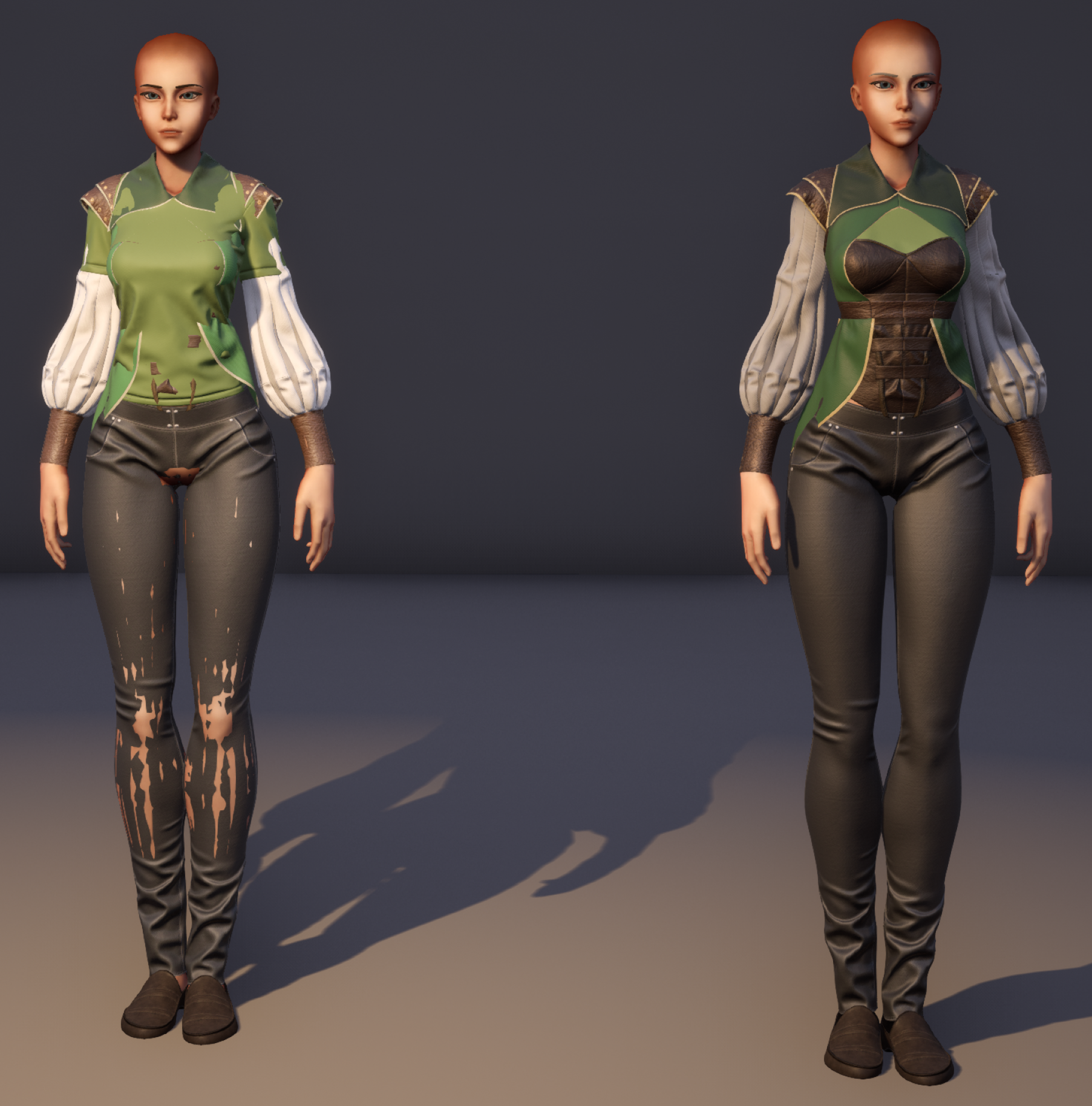
Table of Contents Character Clothing Zone Culling Character Clothing – Part 2: Maya Character Clothing – Part 3: UE4 Shaders Character Clothing – Part 4: UE4 Logic Introduction When developing characters with multiple layers of clothing, it is very possible you’ll end up with this sort of issue: As you apply layers of clothing, you may find that the layers intersect and clip. What you’d really like this: A common approach to solve this is to develop all the mesh combinations you need as separate meshes, like so: Each of these is a separate mesh This can lead to restricting clothing designs and shapes and colossal amounts of geometry files to cope with all the variations. But there is a better way! One solution I’ve found particularly interesting is how Star Citizen handle it. They break their clothes down into sections that can each be toggled on/off as needed, based on the combination of clothing applied. I will now show you how to implement such a system in Unreal Engine 4 (though the approach is completely doable in Unity, too). This system will enable you to layer up clothing and hide any sections of those layers so that they no longer clip. The system is flexible and supports, in theory, an infinite amount of culling zones (although, that might become unmanageable from an artists’s workflow perspective). Performance cost should also be improved. Although all your vertices will be processed, they won’t need drawing. As a result you’ll have less to draw, less to light and less to process overall. Requirements We’ll need a few things to get started. Unreal Engine 4. Any recent version should do A modelling tool. We’ll be using Maya here, but as long as you can have multiple UV sets/channels, you’ll be good Preparation We’ll introduce you to a few topics in this tutorial that will make this process possible. First off, we need to figure out how to cull parts of the mesh dynamically in a nice, optimised & efficient way, then we need to figure out how to define an area to cull and finally implement this in a nice way in Unreal Engine 4 so that an artist can control, per piece of clothing, which sections to hide underneath. In order to figure out our best approach we need to consider the way we want to author the clothing content. The desired workflow: We want an artist to make a item of clothing, such as a leather jacket, a t-shirt or a vest as they normally would. Import those as individual items into the game project. Layer up the clothing. Then, be able to configure each layer item with a value that tells our shader what parts of each layer to mask (all demonstrated in the Star Citizen video) Some Theory As discussed, it isn’t practical to pre-calculate variations of a mesh with every possible other combination of clothing layering. We need to be able to cull dynamically within a mesh’s vertex shader. For culling, there’s a small feature within vertex shaders we can use to our advantage: If a vertex’s position is either infinity or not a number (referred to as “NaN“), the renderer will just cull it. So, if we know which vertices the hide, we’ll be able to do that within the shader. Dividing the vertices’ position by 0 will do just fine: if(cullThisVertex) { // Dividing by 0 is a great way to break a value // This vertex will no longer be drawn vertex.position = vertex.position / 0.0; } We know how to cull the vertices – but a larger problem is still looming: How do we know which areas to cull? So, time to figure out how to define those areas to cull in the shader. We want a value we can provide to the vertex shader that will know how to cull each zone. This is where bitmasks come in. A Short Introduction to Bitmasks: This part is heavy. Basically bitmasks allow us to manipulate the way computers store numbers in such a way as we can create a list of things to show/hide. Tangent #1 – Bitmasks There are two things to keep in mind: Modern consumer-grade GPUs only support 32-bit unsigned integers. This means that for each material on our character/clothing, we can only have 32 zones for culling. If you’re using Unreal Engine 4, you will be limited to 24 zones. This is because you can’t pass integers, or unsigned integers to a Material without modifying the Engine – you can only pass floats, which are stored differently in memory than integers. You can get around these limitations by breaking your meshes up. For example, separate the head, upper and lower-parts of your body. This means for each of these, you get your full zoning allocation. For this to work, you can’t have single clothing pieces across these separations, such as with overalls or jumpsuits without additional work outside the scope of this tutorial. Continue on to the next page: Character Clothing – Part 2: Maya
Approximating Thin Film Interference
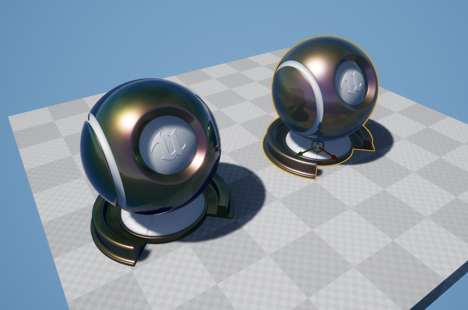
Thin Film Interference is an optical effect caused by the constructive & destructive interference of light waves as they pass through a thing medium. This only occurs when the thickness of the film is in the range of visible light (so 380nm-780nm, approximately). This video is marginally tangential, but explains the basics well: The paper is fantastic, and the results have since been implemented in Unity & UE4. However, the shader is expensive. Whilst it is a practical and wonderfully accurate shader, it would not be something I would suggest for lower-end platforms. Realtime thin film interference is heading towards bad. Data Extraction What I wanted to do was to find a reasonable way of approximating the colous and results from the shader, but at less expense. The first step is to extract the effect to individual planar tiles, so that we can break down what the physical values in the shader produce in isolation. The next step was to make the inputs for Dinc (thickness), n2, n3 and k3 based off UV coordinated and world space coordinates – that way, I can arrange planes in a grid to use as a look-up texture. For this example, I fixed the normal to be (0,0,1) and the light direction to be (0,0,1). And this is the scene setup – each one of these is a plane, set to 16.0 scale in the X-axis. They tile across the +X and -Y axis. I then took a High Resolution Screenshot of this to create a look-up texture, like so: As you can see, the changes in brightness and saturation all vary based on the input properties – it appears subtle, but it adds up across the range of possible values. There is, however, one more value we can’t fit into a LUT – the viewing angle. This also has an impact on the final colors – I’ve exposed the light direction here to hopefully show the impact it has: Changing the Light Direction We can simulate this effect by offsetting our UVs later. I imported the LUT setting ‘No Mipmaps’ and ‘Nearest’ filter, as we want no blurring between the grid cells. Approximating I then set it a new Material in such a way that the input values for Dinc, n2, n3 and k3 all correspond to UV coordinates in the LUT – I use a Fresnel function (dot(N,L)) to sample the LUT. Where you see the inputs in the Material Graph, the next few nodes for each are simply remapping the value ranges into UV space. I sample the texture twice for k3 and blend between the two samples, as one sample didn’t give me enough precision. Next, I added in option use a thickness mask, or a thickness value. Finally, to mask the effect, we need to multiply our underlying base color by the thin film color, as the light waves bouncing off the underlying surface will only reflect back with that surface color. We then blend this using a mask, so we can mask out areas we don’t wish to apply the film effect. The full Material Results We can now achieve some mightily convincing results: And if you want to really go-to-town, this sort of thing is completely possible: And there is also a difference in instructions: from 440, down to 198, and this difference doesn’t even account for the fact that the more expensive shader hasn’t had support for film thickness mask etc. added yet… Shader complexity view: Concluding Notes My implementation isn’t full simulation – its not designed for physically-accurate work. It is, however, close, and more importantly, cheap – enough for mobile/low-end applications if you can handle the additional memory requirements for the LUT.